PET scanner geometries parallelproj.pet_scanners
The scanner geometry is the first link in the projector construction chain, and which scanner class you pick selects one of the two projector routes (see PET projectors parallelproj.projectors):
Cylindrical scanners with a single layer of LOR endpoints (the most common case): use
RegularPolygonPETScannerGeometry, orDemoPETScannerGeometryfor a ready-made example. These feed the regular-polygon route (viaMichelogramandRegularPolygonPETLORDescriptor).General modular scanners (block / panel geometries, or anything without cylindrical symmetry): build a
ModularizedPETScannerGeometryfromBlockPETScannerModuleobjects, which feeds the equal-block route (viaEqualBlockPETLORDescriptor).
The array backend xp and device dev passed here determine where all
downstream computation runs (CPU or GPU). See Quickstart for a runnable
example of the regular-polygon route.
PET scanner geometry classes describing detector module layouts and endpoint coordinates.
Covers both modular scanners (ModularizedPETScannerGeometry, where
modules can be placed arbitrarily) and the regular-polygon scanner
(RegularPolygonPETScannerGeometry), which is the primary geometry
used throughout parallelproj. Provides methods for computing LOR endpoint
world coordinates and visualising the detector arrangement.
- class parallelproj.pet_scanners.BlockPETScannerModule(xp: ModuleType, dev: str, shape: tuple[int, int, int], spacing: tuple[float, float, float], affine_transformation_matrix: Array | None = None)[source]
Bases:
PETScannerModuleBlock (rectangular cuboid) PET scanner module
Examples

Non-TOF and TOF projections using a modularized (block) PET scanner geometry
Non-TOF and TOF projections using a modularized (block) PET scanner geometry- Parameters:
xp (ModuleType) – array module to use for storing the LOR endpoints
dev (str) – device to use for storing the LOR endpoints
shape (tuple[int, int, int]) – shape of the regular grid of LOR endpoints forming the block module
spacing (tuple[float, float, float]) – spacing between the LOR endpoints in each direction
affine_transformation_matrix (Array | None, optional) – 4x4 affine transformation matrix applied eagerly to the LOR endpoint coordinates at construction time. The transformed positions are stored directly; the matrix itself is not retained, so subsequent calls to
get_lor_endpoints()apply no further transform.None(default) leaves the endpoints in their local frame.
Examples
Non-TOF and TOF projections using a modularized (block) PET scanner geometry
Non-TOF and TOF projections using a modularized (block) PET scanner geometry- property affine_transformation_matrix: Array
4x4 affine transformation matrix
- Returns:
4x4 identity matrix if no transformation was provided
- Return type:
Array
- property dev: str
device to use for storing the LOR endpoints
- get_lor_endpoints(inds: Array | None = None) Array
mapping from LOR endpoint indices within module to an array of “transformed” world coordinates
- Parameters:
inds (Array | None, optional) – an non-negative integer array of indices, default None if None means all possible indices [0, … , num_lor_endpoints - 1]
- Returns:
float array of shape (len(inds), 3) with the world coordinates of the LOR endpoints after applying the affine transformation (if any)
- Return type:
Array
Examples
- get_raw_lor_endpoints(inds: Array | None = None) Array[source]
Return world coordinates of the requested crystal endpoints.
Looks up pre-computed endpoint positions from the stored grid array.
- Parameters:
inds (Array | None, optional) – Integer indices into the module’s endpoint list.
Nonereturns all endpoints (default).- Returns:
Float array of shape
(len(inds), 3)with world coordinates.- Return type:
Array
Examples
- property lor_endpoint_numbers: Array
array enumerating all the LOR endpoints in the module
- Return type:
Array
- property lor_endpoints: Array
LOR endpoints of the block module
- Return type:
Array
- property num_lor_endpoints: int
total number of LOR endpoints in the module
- Return type:
int
- property shape: tuple[int, int, int]
shape of the block module
- Return type:
tuple[int, int, int]
- show_lor_endpoints(ax: Axes3D, annotation_fontsize: float = 0, annotation_prefix: str = '', annotation_offset: int = 0, transformed: bool = True, **kwargs) None
show the LOR coordinates in a 3D scatter plot
- Parameters:
ax (Axes3D) – 3D matplotlib axes
annotation_fontsize (float, optional) – fontsize of LOR endpoint number annotation, by default 0
annotation_prefix (str, optional) – prefix for annotation, by default ‘’
annotation_offset (int, optional) – number to add to crystal number, by default 0
transformed (bool, optional) – use transformed instead of raw coordinates, by default True
- Return type:
None
Examples
- property spacing: tuple[float, float, float]
spacing of the block module
- Return type:
tuple[float, float, float]
- property xp: ModuleType
array module to use for storing the LOR endpoints

- class parallelproj.pet_scanners.DemoPETScannerGeometry(xp: ModuleType, dev: str, radius: float = 380.56, num_sides: int = 34, num_lor_endpoints_per_side: int = 16, lor_spacing: float = 4.03125, num_rings: int = 36, symmetry_axis: int = 2)[source]
Bases:
RegularPolygonPETScannerGeometryDemo PET scanner geometry consisting of a 34-ogon with 16 LOR endpoints per side and 36 rings
Examples
- Parameters:
xp (ModuleType) – array module
dev (str) – the device to use
radius (float, optional) – radius of the regular polygon, by default 0.5*(744.1 + 2 * 8.51)
num_sides (int, optional) – number of sides of the polygon, by default 34
num_lor_endpoints_per_side (int, optional) – number of LOR endpoints per side, by default 16
lor_spacing (float, optional) – spacing between the LOR endpoints, by default 4.03125
num_rings (int, optional) – number of rings, by default 36
symmetry_axis (int, optional) – symmetry (axial) axis of the scanner, by default 2
Examples
- property all_lor_endpoints: Array
the world coordinates of all LOR endpoints
- property all_lor_endpoints_index_in_ring: Array
the index within the ring (regular polygon) of all LOR endpoints
- property all_lor_endpoints_index_offset: Array
the offset in the linear (flattend) index for all LOR endpoints
- property all_lor_endpoints_module_number: Array
the module number of all LOR endpoints
- property all_lor_endpoints_ring_number: Array
Ring (axial module) index for every LOR endpoint.
For a regular-polygon scanner each axial ring is one module, so this is an alias for
all_lor_endpoints_module_number. Values range from0tonum_rings - 1.
- property dev: str
Device of the first module.
All modules in the scanner must reside on the same device; this property returns the device of the first one as representative.
- get_lor_endpoints(module: Array, index_in_module: Array) Array
get the coordinates for LOR endpoints defined by module and index in module
- Parameters:
module (Array) – the module number of the LOR endpoints
index_in_module (Array) – the index in module number of the LOR endpoints
- Returns:
the 3 world coordinates of the LOR endpoints
- Return type:
Array
Examples
- linear_lor_endpoint_index(module: Array, index_in_module: Array) Array
transform the module + index_in_modules indices into a flattened / linear LOR endpoint index
- Parameters:
module (Array) – containing module numbers
index_in_module (Array) – containing index in modules
- Returns:
the flattened LOR endpoint index
- Return type:
Array
Examples
- property lor_endpoint_positions: Array
1-D float32 Array of crystal positions along each polygon side (mm), on the same device as the scanner.
- property lor_spacing: float | None
Uniform spacing between LOR endpoints in mm, or
Nonewhen customlor_endpoint_positionswere supplied.
- property modules: Sequence[PETScannerModule]
sequence of modules defining the scanner
- property num_lor_endpoints: int
the total number of LOR endpoints in the scanner
- property num_lor_endpoints_per_module: Array
array showing how many LOR endpoints are in every module
- property num_lor_endpoints_per_ring: int
the number of LOR endpoints per ring (regular polygon)
- property num_lor_endpoints_per_side: int
number of LOR endpoints per side (face) in each polygon
- property num_modules: int
the number of modules defining the scanner
- property num_rings: int
number of rings (regular polygons)
- property num_sides: int
number of sides (faces) of each polygon
- property phi0: float
azimuthal offset of side 0 in radians (only applied when phis=None)
- property radius: float
Inner radius of the regular polygon (distance from centre to detector face) in mm.
- property ring_endpoint_ordering: RingEndpointOrdering
direction in which endpoint indices increase around the ring
- property ring_positions: Array
the ring (regular polygon) positions
- setup_all_lor_endpoints() None
calculate the position of all lor endpoints by iterating over the modules and calculating the transformed coordinates of all module endpoints
Examples
- Return type:
None
- show_lor_endpoints(ax: Axes3D, show_linear_index: bool = True, **kwargs) None
show all LOR endpoints in a 3D plot
- Parameters:
ax (Axes3D) – a 3D matplotlib axes
show_linear_index (bool, optional) – annotate the LOR endpoints with the linear LOR endpoint index
**kwargs (keyword arguments) – passed to show_lor_endpoints() of the scanner module
- Return type:
None
Examples
- property symmetry_axis: int
The symmetry axis. Also called axial (or ring) direction.
- property xp: ModuleType
Array module of the first module.
All modules in the scanner must share the same array namespace; this property returns the namespace of the first one as representative.
- class parallelproj.pet_scanners.ModularizedPETScannerGeometry(modules: Sequence[PETScannerModule])[source]
Bases:
objectA PET scanner geometry built from an ordered list of
PETScannerModuleobjects.Each module contributes a contiguous block of LOR endpoints to the global flat index space. The global index of endpoint
kin moduleiisall_lor_endpoints_index_offset[i] + k. All modules must share the same array namespace (xp) and device.Use
RegularPolygonPETScannerGeometryfor the common case of a cylindrical scanner with stacked regular-polygon rings. Use this class directly when the scanner has an irregular or custom module layout.Examples
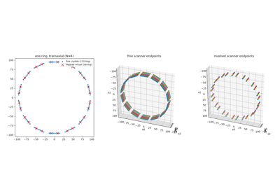
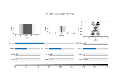
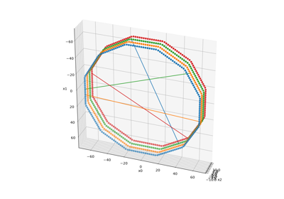
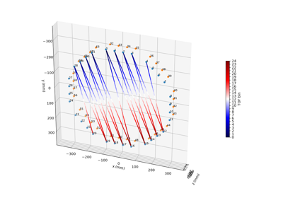
Non-TOF and TOF projections using a modularized (block) PET scanner geometry
Non-TOF and TOF projections using a modularized (block) PET scanner geometry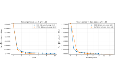
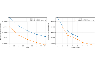
Convergence comparison: SGD vs SVRG with logcosh regularization
Convergence comparison: SGD vs SVRG with logcosh regularization
PDHG and SPDHG for PET reconstruction with a directional TV prior
PDHG and SPDHG for PET reconstruction with a directional TV prior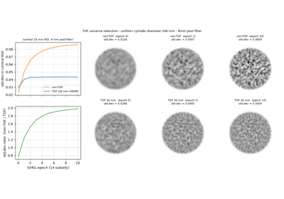
TOF vs non-TOF: variance reduction in a uniform cylinder
TOF vs non-TOF: variance reduction in a uniform cylinder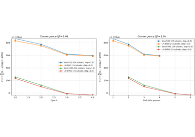
Convergence comparison: SGD vs SVRG with regularization (sinogram and listmode)
Convergence comparison: SGD vs SVRG with regularization (sinogram and listmode)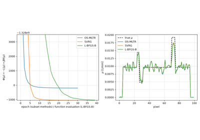
Penalised transmission reconstruction (MAPTR) with an edge-preserving prior
Penalised transmission reconstruction (MAPTR) with an edge-preserving prior- Parameters:
modules (Sequence[PETScannerModule]) – a sequence of scanner modules
Examples
Non-TOF and TOF projections using a modularized (block) PET scanner geometry
Non-TOF and TOF projections using a modularized (block) PET scanner geometry
Convergence comparison: SGD vs SVRG with logcosh regularization
Convergence comparison: SGD vs SVRG with logcosh regularization
PDHG and SPDHG for PET reconstruction with a directional TV prior
PDHG and SPDHG for PET reconstruction with a directional TV prior
TOF vs non-TOF: variance reduction in a uniform cylinder
TOF vs non-TOF: variance reduction in a uniform cylinder
Convergence comparison: SGD vs SVRG with regularization (sinogram and listmode)
Convergence comparison: SGD vs SVRG with regularization (sinogram and listmode)
Penalised transmission reconstruction (MAPTR) with an edge-preserving prior
Penalised transmission reconstruction (MAPTR) with an edge-preserving prior- property all_lor_endpoints: Array
the world coordinates of all LOR endpoints
- property all_lor_endpoints_index_offset: Array
the offset in the linear (flattend) index for all LOR endpoints
- property all_lor_endpoints_module_number: Array
the module number of all LOR endpoints
- property dev: str
Device of the first module.
All modules in the scanner must reside on the same device; this property returns the device of the first one as representative.
- get_lor_endpoints(module: Array, index_in_module: Array) Array[source]
get the coordinates for LOR endpoints defined by module and index in module
- Parameters:
module (Array) – the module number of the LOR endpoints
index_in_module (Array) – the index in module number of the LOR endpoints
- Returns:
the 3 world coordinates of the LOR endpoints
- Return type:
Array
Examples
- linear_lor_endpoint_index(module: Array, index_in_module: Array) Array[source]
transform the module + index_in_modules indices into a flattened / linear LOR endpoint index
- Parameters:
module (Array) – containing module numbers
index_in_module (Array) – containing index in modules
- Returns:
the flattened LOR endpoint index
- Return type:
Array
Examples
- property modules: Sequence[PETScannerModule]
sequence of modules defining the scanner
- property num_lor_endpoints: int
the total number of LOR endpoints in the scanner
- property num_lor_endpoints_per_module: Array
array showing how many LOR endpoints are in every module
- property num_modules: int
the number of modules defining the scanner
- setup_all_lor_endpoints() None[source]
calculate the position of all lor endpoints by iterating over the modules and calculating the transformed coordinates of all module endpoints
Examples
- Return type:
None
- show_lor_endpoints(ax: Axes3D, show_linear_index: bool = True, **kwargs) None[source]
show all LOR endpoints in a 3D plot
- Parameters:
ax (Axes3D) – a 3D matplotlib axes
show_linear_index (bool, optional) – annotate the LOR endpoints with the linear LOR endpoint index
**kwargs (keyword arguments) – passed to show_lor_endpoints() of the scanner module
- Return type:
None
Examples
- property xp: ModuleType
Array module of the first module.
All modules in the scanner must share the same array namespace; this property returns the namespace of the first one as representative.





- class parallelproj.pet_scanners.PETScannerModule(xp: ModuleType, dev: str, num_lor_endpoints: int, affine_transformation_matrix: Array | None = None)[source]
Bases:
ABCAbstract base class for a single detector module in a PET scanner.
A module groups a fixed number of LOR endpoints (detector elements) and exposes their world coordinates via
get_raw_lor_endpoints()(before any affine transform) andget_lor_endpoints()(after). An optional 4x4 affine transformation matrix can be supplied to reposition the module in world space.Concrete subclasses:
BlockPETScannerModule– a 3-D rectangular grid of crystalsRegularPolygonPETScannerModule– one flat side of a regular-polygon scanner
Examples
Non-TOF and TOF projections using a modularized (block) PET scanner geometry
Non-TOF and TOF projections using a modularized (block) PET scanner geometry- Parameters:
xp (ModuleType) – array module to use for storing the LOR endpoints
dev (str) – device to use for storing the LOR endpoints
num_lor_endpoints (int) – number of LOR endpoints in the module
affine_transformation_matrix (Array | None, optional) – 4x4 affine transformation matrix applied to the LOR endpoint coordinates, default None if None, the 4x4 identity matrix is used
Examples
Non-TOF and TOF projections using a modularized (block) PET scanner geometry
Non-TOF and TOF projections using a modularized (block) PET scanner geometry- property affine_transformation_matrix: Array
4x4 affine transformation matrix
- Returns:
4x4 identity matrix if no transformation was provided
- Return type:
Array
- property dev: str
device to use for storing the LOR endpoints
- get_lor_endpoints(inds: Array | None = None) Array[source]
mapping from LOR endpoint indices within module to an array of “transformed” world coordinates
- Parameters:
inds (Array | None, optional) – an non-negative integer array of indices, default None if None means all possible indices [0, … , num_lor_endpoints - 1]
- Returns:
float array of shape (len(inds), 3) with the world coordinates of the LOR endpoints after applying the affine transformation (if any)
- Return type:
Array
Examples
- abstractmethod get_raw_lor_endpoints(inds: Array | None = None) Array[source]
mapping from LOR endpoint indices within module to an array of “raw” world coordinates
- Parameters:
inds (Array | None, optional) – an non-negative integer array of indices, default None if None means all possible indices [0, … , num_lor_endpoints - 1]
- Returns:
float array of shape (len(inds), 3) with the world coordinates of the LOR endpoints
- Return type:
Array
Examples
- property lor_endpoint_numbers: Array
array enumerating all the LOR endpoints in the module
- Return type:
Array
- property num_lor_endpoints: int
total number of LOR endpoints in the module
- Return type:
int
- show_lor_endpoints(ax: Axes3D, annotation_fontsize: float = 0, annotation_prefix: str = '', annotation_offset: int = 0, transformed: bool = True, **kwargs) None[source]
show the LOR coordinates in a 3D scatter plot
- Parameters:
ax (Axes3D) – 3D matplotlib axes
annotation_fontsize (float, optional) – fontsize of LOR endpoint number annotation, by default 0
annotation_prefix (str, optional) – prefix for annotation, by default ‘’
annotation_offset (int, optional) – number to add to crystal number, by default 0
transformed (bool, optional) – use transformed instead of raw coordinates, by default True
- Return type:
None
Examples
- property xp: ModuleType
array module to use for storing the LOR endpoints
- class parallelproj.pet_scanners.RegularPolygonPETScannerGeometry(xp: ModuleType, dev: str, radius: float, num_sides: int, ring_positions: Array, symmetry_axis: int, *, num_lor_endpoints_per_side: int | None = None, lor_spacing: float | None = None, phis: None | Array = None, ring_endpoint_ordering: RingEndpointOrdering = RingEndpointOrdering.CLOCKWISE, phi0: float = 0.0, lor_endpoint_positions: Array | None = None)[source]
Bases:
ModularizedPETScannerGeometryA cylindrical PET scanner built from stacked regular-polygon rings.
Each axial ring is a
RegularPolygonPETScannerModulewithnum_sidessides andnum_lor_endpoints_per_sidecrystals per side, givingnum_lor_endpoints_per_ring = num_sides * num_lor_endpoints_per_sideendpoints per ring. Rings are stacked axially; the global flat endpoint index increases first within a ring and then across rings, so endpointr * num_lor_endpoints_per_ring + kbelongs to ringrand in-ring positionk.Examples
Convergence comparison: SGD vs SVRG with logcosh regularization
Convergence comparison: SGD vs SVRG with logcosh regularization
PDHG and SPDHG for PET reconstruction with a directional TV prior
PDHG and SPDHG for PET reconstruction with a directional TV prior
TOF vs non-TOF: variance reduction in a uniform cylinder
TOF vs non-TOF: variance reduction in a uniform cylinder
Convergence comparison: SGD vs SVRG with regularization (sinogram and listmode)
Convergence comparison: SGD vs SVRG with regularization (sinogram and listmode)
PDHG and LM-SPDHG to optimize the Poisson logL and total variation
PDHG and LM-SPDHG to optimize the Poisson logL and total variation
Transmission reconstruction: MLTR, SPS and L-BFGS-B
Transmission reconstruction: MLTR, SPS and L-BFGS-B
Accelerating MLTR with ordered subsets (OS-MLTR) and SVRG
Accelerating MLTR with ordered subsets (OS-MLTR) and SVRG
Penalised transmission reconstruction (MAPTR) with an edge-preserving prior
Penalised transmission reconstruction (MAPTR) with an edge-preserving prior
Joint activity and attenuation reconstruction (MLAA) for TOF PET
Joint activity and attenuation reconstruction (MLAA) for TOF PET- Parameters:
xp (ModuleType) – array module to use for storing the LOR endpoints
dev (str) – device to use for storing the LOR endpoints
radius (float) – inner radius of the regular polygon (distance from centre to detector face) in mm
num_sides (int) – number of sides (faces) of each regular polygon
ring_positions (Array) – 1D array with the coordinate of the rings along the ring axis
symmetry_axis (int) – the ring axis (0,1,2)
num_lor_endpoints_per_side (int or None, optional) – number of LOR endpoints in each side. Required when
lor_endpoint_positionsis not given; ignored otherwise.lor_spacing (float or None, optional) – uniform spacing between LOR endpoints in mm. Required when
lor_endpoint_positionsis not given; ignored otherwise.phis (None | Array, optional) – angle of each side, by default None means that the sides are equally spaced around a circle
ring_endpoint_ordering (RingEndpointOrdering, optional) – direction in which endpoint indices increase around the ring, by default
RingEndpointOrdering.CLOCKWISE.phi0 (float, optional) – azimuthal offset of side 0 in radians, by default 0. With the default (and
symmetry_axis=2) side 0 is centred on the -y axis, which is the “top” of the default 3D view (viewed from -z with +y pointing down). A positivephi0is a right-hand rotation about the symmetry axis, i.e. forsymmetry_axis=2it moves side 0 toward +x. Only applied whenphisisNone; ignored whenphisis provided explicitly.lor_endpoint_positions (Array or None, optional) – Custom 1-D array of crystal positions along each polygon side in mm. When given, overrides
num_lor_endpoints_per_sideandlor_spacing. SeeRegularPolygonPETScannerModulefor details and anti-symmetry requirements.
Examples
Convergence comparison: SGD vs SVRG with logcosh regularization
Convergence comparison: SGD vs SVRG with logcosh regularization
PDHG and SPDHG for PET reconstruction with a directional TV prior
PDHG and SPDHG for PET reconstruction with a directional TV prior
TOF vs non-TOF: variance reduction in a uniform cylinder
TOF vs non-TOF: variance reduction in a uniform cylinder
Convergence comparison: SGD vs SVRG with regularization (sinogram and listmode)
Convergence comparison: SGD vs SVRG with regularization (sinogram and listmode)
PDHG and LM-SPDHG to optimize the Poisson logL and total variation
PDHG and LM-SPDHG to optimize the Poisson logL and total variation
Transmission reconstruction: MLTR, SPS and L-BFGS-B
Transmission reconstruction: MLTR, SPS and L-BFGS-B
Accelerating MLTR with ordered subsets (OS-MLTR) and SVRG
Accelerating MLTR with ordered subsets (OS-MLTR) and SVRG
Penalised transmission reconstruction (MAPTR) with an edge-preserving prior
Penalised transmission reconstruction (MAPTR) with an edge-preserving prior
Joint activity and attenuation reconstruction (MLAA) for TOF PET
Joint activity and attenuation reconstruction (MLAA) for TOF PET- property all_lor_endpoints: Array
the world coordinates of all LOR endpoints
- property all_lor_endpoints_index_in_ring: Array
the index within the ring (regular polygon) of all LOR endpoints
- property all_lor_endpoints_index_offset: Array
the offset in the linear (flattend) index for all LOR endpoints
- property all_lor_endpoints_module_number: Array
the module number of all LOR endpoints
- property all_lor_endpoints_ring_number: Array
Ring (axial module) index for every LOR endpoint.
For a regular-polygon scanner each axial ring is one module, so this is an alias for
all_lor_endpoints_module_number. Values range from0tonum_rings - 1.
- property dev: str
Device of the first module.
All modules in the scanner must reside on the same device; this property returns the device of the first one as representative.
- get_lor_endpoints(module: Array, index_in_module: Array) Array
get the coordinates for LOR endpoints defined by module and index in module
- Parameters:
module (Array) – the module number of the LOR endpoints
index_in_module (Array) – the index in module number of the LOR endpoints
- Returns:
the 3 world coordinates of the LOR endpoints
- Return type:
Array
Examples
- linear_lor_endpoint_index(module: Array, index_in_module: Array) Array
transform the module + index_in_modules indices into a flattened / linear LOR endpoint index
- Parameters:
module (Array) – containing module numbers
index_in_module (Array) – containing index in modules
- Returns:
the flattened LOR endpoint index
- Return type:
Array
Examples
- property lor_endpoint_positions: Array
1-D float32 Array of crystal positions along each polygon side (mm), on the same device as the scanner.
- property lor_spacing: float | None
Uniform spacing between LOR endpoints in mm, or
Nonewhen customlor_endpoint_positionswere supplied.
- property modules: Sequence[PETScannerModule]
sequence of modules defining the scanner
- property num_lor_endpoints: int
the total number of LOR endpoints in the scanner
- property num_lor_endpoints_per_module: Array
array showing how many LOR endpoints are in every module
- property num_lor_endpoints_per_ring: int
the number of LOR endpoints per ring (regular polygon)
- property num_lor_endpoints_per_side: int
number of LOR endpoints per side (face) in each polygon
- property num_modules: int
the number of modules defining the scanner
- property num_rings: int
number of rings (regular polygons)
- property num_sides: int
number of sides (faces) of each polygon
- property phi0: float
azimuthal offset of side 0 in radians (only applied when phis=None)
- property radius: float
Inner radius of the regular polygon (distance from centre to detector face) in mm.
- property ring_endpoint_ordering: RingEndpointOrdering
direction in which endpoint indices increase around the ring
- property ring_positions: Array
the ring (regular polygon) positions
- setup_all_lor_endpoints() None
calculate the position of all lor endpoints by iterating over the modules and calculating the transformed coordinates of all module endpoints
Examples
- Return type:
None
- show_lor_endpoints(ax: Axes3D, show_linear_index: bool = True, **kwargs) None
show all LOR endpoints in a 3D plot
- Parameters:
ax (Axes3D) – a 3D matplotlib axes
show_linear_index (bool, optional) – annotate the LOR endpoints with the linear LOR endpoint index
**kwargs (keyword arguments) – passed to show_lor_endpoints() of the scanner module
- Return type:
None
Examples
- property symmetry_axis: int
The symmetry axis. Also called axial (or ring) direction.
- property xp: ModuleType
Array module of the first module.
All modules in the scanner must share the same array namespace; this property returns the namespace of the first one as representative.
- class parallelproj.pet_scanners.RegularPolygonPETScannerModule(xp: ModuleType, dev: str, radius: float, num_sides: int, num_lor_endpoints_per_side: int | None = None, lor_spacing: float | None = None, ax0: int = 2, ax1: int = 1, affine_transformation_matrix: Array | None = None, phis: None | Array = None, ring_endpoint_ordering: RingEndpointOrdering = RingEndpointOrdering.CLOCKWISE, phi0: float = 0.0, lor_endpoint_positions: Array | None = None)[source]
Bases:
PETScannerModuleRegular polygon PET scanner module (detectors on a regular polygon)
Examples
- Parameters:
xp (ModuleType) – array module to use for storing the LOR endpoints
dev (str) – device to use for storing the LOR endpoints
radius (float) – inner radius of the regular polygon
num_sides (int) – number of sides of the regular polygon
num_lor_endpoints_per_side (int or None, optional) – number of LOR endpoints per side. Required when
lor_endpoint_positionsis not given; ignored otherwise.lor_spacing (float or None, optional) – uniform spacing between LOR endpoints in mm. Required when
lor_endpoint_positionsis not given; ignored otherwise.ax0 (int, optional) – axis number for the first direction, by default 2
ax1 (int, optional) – axis number for the second direction, by default 1
affine_transformation_matrix (Array | None, optional) – 4x4 affine transformation matrix applied to the LOR endpoint coordinates, default None if None, the 4x4 identity matrix is used
phis (None | Array, optional) – angle of each side, by default None means that the sides are equally spaced around a circle
ring_endpoint_ordering (RingEndpointOrdering, optional) – direction in which endpoint indices increase around the ring, by default
RingEndpointOrdering.CLOCKWISE.phi0 (float, optional) – azimuthal offset of side 0 in radians, by default 0. With the default (and
symmetry_axis=2) side 0 is centred on the -y axis, which is the “top” of the default 3D view (viewed from -z with +y pointing down). A positivephi0is a right-hand rotation about the symmetry axis, i.e. forsymmetry_axis=2it moves side 0 toward +x. Only applied whenphisisNone; ignored whenphisis provided explicitly.lor_endpoint_positions (Array or None, optional) –
1-D array of crystal positions (in mm) along each polygon side, with 0 at the centre of the side. When given, overrides
num_lor_endpoints_per_sideandlor_spacing.For radial sinogram symmetry to hold (see
build_radial_class_indices()), the array must be anti-symmetric about 0:pos[i] == -pos[N-1-i]for alli. AUserWarningis issued if this condition is not met.Examples for a side with even N=6 (3 crystals each half, uniform 2 mm pitch, 1 mm gap):
lor_endpoint_positions = xp.asarray(
    [-3.5, -1.5, -0.5, 0.5, 1.5, 3.5], device=dev
)
Examples for odd N=5 (2 crystals each half + one centre crystal, uniform 2 mm pitch):
lor_endpoint_positions = xp.asarray(
    [-4.0, -2.0, 0.0, 2.0, 4.0], device=dev
)
Examples
- property affine_transformation_matrix: Array
4x4 affine transformation matrix
- Returns:
4x4 identity matrix if no transformation was provided
- Return type:
Array
- property ax0: int
axis number for the first module direction
- Return type:
int
- property ax1: int
axis number for the second module direction
- Return type:
int
- property dev: str
device to use for storing the LOR endpoints
- get_lor_endpoints(inds: Array | None = None) Array
mapping from LOR endpoint indices within module to an array of “transformed” world coordinates
- Parameters:
inds (Array | None, optional) – an non-negative integer array of indices, default None if None means all possible indices [0, … , num_lor_endpoints - 1]
- Returns:
float array of shape (len(inds), 3) with the world coordinates of the LOR endpoints after applying the affine transformation (if any)
- Return type:
Array
Examples
- get_raw_lor_endpoints(inds: Array | None = None) Array[source]
Compute world coordinates for the requested crystal endpoints.
Calculates endpoint positions analytically from the scanner geometry (radius, number of sides, crystals per side, azimuthal offset), respecting the configured
RingEndpointOrdering.- Parameters:
inds (Array | None, optional) – Integer indices into the module’s endpoint list.
Nonereturns all endpoints (default).- Returns:
Float array of shape
(len(inds), 3)with world coordinates.- Return type:
Array
Examples
- property lor_endpoint_numbers: Array
array enumerating all the LOR endpoints in the module
- Return type:
Array
- property lor_endpoint_positions: Array
1-D float32 Array of crystal positions along each polygon side (mm), on the same device as the scanner.
Anti-symmetric about 0 for standard scanners (uniform or gap layout).
- property lor_spacing: float | None
Uniform spacing between LOR endpoints in mm, or
Nonewhen customlor_endpoint_positionswere supplied.
- property num_lor_endpoints: int
total number of LOR endpoints in the module
- Return type:
int
- property num_lor_endpoints_per_side: int
number of LOR endpoints per side
- Return type:
int
- property num_sides: int
number of sides of the regular polygon
- Return type:
int
- property phi0: float
azimuthal offset of side 0 in radians (only applied when phis=None)
- property phis: Array
azimuthal angle of each side
- Return type:
Array
- property radius: float
inner radius of the regular polygon
- Return type:
float
- property ring_endpoint_ordering: RingEndpointOrdering
direction in which endpoint indices increase around the ring
- show_lor_endpoints(ax: Axes3D, annotation_fontsize: float = 0, annotation_prefix: str = '', annotation_offset: int = 0, transformed: bool = True, **kwargs) None
show the LOR coordinates in a 3D scatter plot
- Parameters:
ax (Axes3D) – 3D matplotlib axes
annotation_fontsize (float, optional) – fontsize of LOR endpoint number annotation, by default 0
annotation_prefix (str, optional) – prefix for annotation, by default ‘’
annotation_offset (int, optional) – number to add to crystal number, by default 0
transformed (bool, optional) – use transformed instead of raw coordinates, by default True
- Return type:
None
Examples
- property xp: ModuleType
array module to use for storing the LOR endpoints
- class parallelproj.pet_scanners.RingEndpointOrdering(*values)[source]
Bases:
EnumDirection in which endpoint indices increase around a detector ring.
The ordering is defined for the standard view of the scanner: looking along the symmetry axis from its negative side toward the positive side (for
symmetry_axis=2this is looking from -z toward +z, the default 3D view, with +x to the right and +y pointing down). Index 0 sits at the 12 o’clock position (the top, i.e. the -y direction forsymmetry_axis=2); the two conventions differ in which way the indices then advance:CLOCKWISEIndices advance clockwise on screen (toward +x first). This is the default.
COUNTERCLOCKWISEIndices advance counterclockwise on screen (toward -x first).
Examples
- CLOCKWISE = 1
Indices increase clockwise (default).
Examples
- COUNTERCLOCKWISE = 2
Indices increase counterclockwise.
Examples
- classmethod __getitem__(name)
Return the member matching name.
Examples